In calibrating our current monitors, we make use of low inductance precision resistors whose resistance value is calibrated with NIST traceable standards. The resistor is constructed of radial manganin wires joining a center conductor to an outer ring in a coaxial structure. The value of resistance used depends on the sensitivity of the current monitor under test. Resistors of 1, 0.1 and 0.01 ohms are available, and for monitors of intermediate sensitivity, multiple turns of the test conductor are used.
A current pulse is generated by a current power supply switched by a transistor switch under control of a pulse generator. The pulse-current passes through the current monitor and through the calibrated low inductance resistor to ground. The voltage drop across the resistor is subtracted from the voltage produced by the Current Monitor and the difference signal is observed on an oscilloscope (Figure 1). This display is used to measure error and droop.
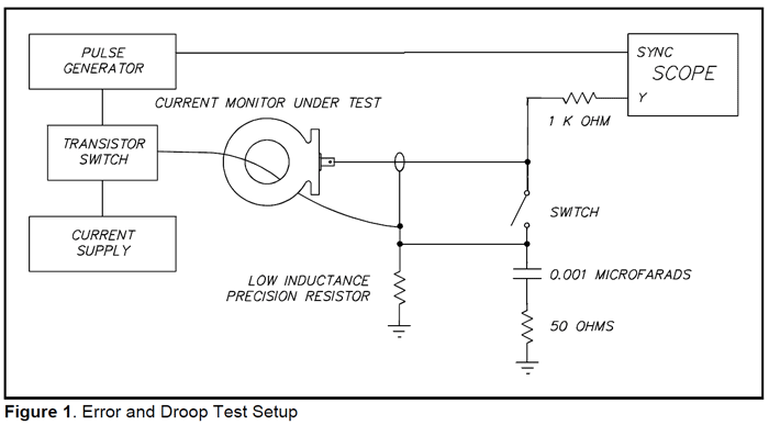
Since the Current Monitors are linear, it is not necessary to use large current pulses. The pulse source which we utilize has settings for 8.0 and 0.8 amperes, and a pulse width of up to 1 millisecond, with a low duty cycle.
All current monitors are tested for rise-time performance at two points in the manufacturing cycle. The test set-up is shown in the accompanying diagram (Figure 2).
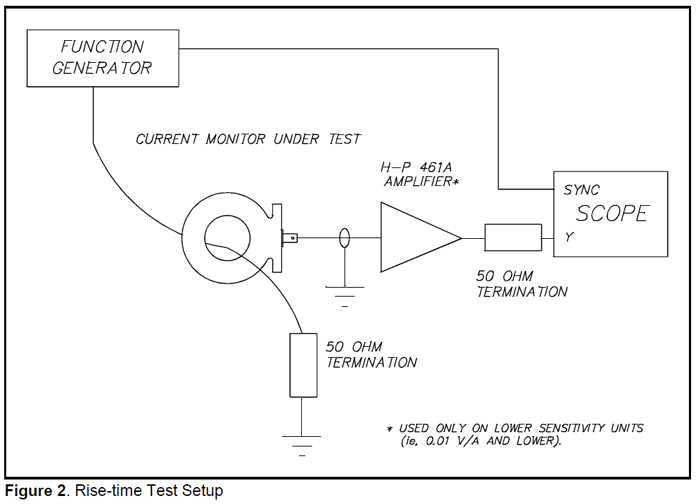
The function generator is the Tektronix FG 504 plug in unit. It is set for square-waveoutput, with a frequency of about 10 kHz. Current from the normal output jack is fed through the unit under test, and to a 50 ohm termination. The current monitor is connected to a second in-line termination at the oscilloscope input. The sync out jack on the function generator is connected to the trigger input of the scope. The Tektronix 2213 oscilloscope is used. For low sensitivity models, the H-P 461A amplifier is used between the Current Monitor and the termination. A setting of 40 dB is usually used.
The variable rise-time feature on the function generator is used for the test. The range setting for this control, as well as the settings for the oscilloscope, are made according to which model is being tested.
The test consists of setting the variable rise-time control so that the leading edge of the square wave shows the rise-time given in the specification sheet for the particular model being tested. The overshoot and ringing must be less than 10% of the squarewave transition amplitude.
The effect of test wire location is then checked by moving the test wire about in the Current Monitor hole. If variations in the waveform occur outside the 10% limit for overshoot and ringing, the unit needs corrective work.